All report-relevant information required to create a full or partial PCF report is recorded in the Base data tab.
The section is divided into two sub-tabs:
1) General information
2) Report configuration
1) General information
Product description:
To calculate the PCF, a concise product description is first recorded that clearly identifies the product under consideration. This description is also output in the final PDF report.
If a product description has already been maintained in the product list, it is automatically transferred when creating a new PCF report. The description can be adjusted within the report if needed. Changes to the product description in the PCF report do not affect the product description in the product list or in other PCF reports.
Selecting the system boundary:
The next step is to define the system boundary. You can choose between different perspectives:
- Cradle-to-gate: Only the phases of raw material acquisition and production up to leaving the factory gate are considered. Distribution, use and end-of-life treatment are not taken into account.
- Cradle-to-grave: Covers the entire life cycle of a product - from the acquisition of raw materials to production, distribution, use and disposal of the product.
Definition of the reference value:
The reference value is defined after the system boundary has been defined.
- Only the declared unit is available for the cradle-to-gate system boundary. It describes the product independently of a defined use, e.g. 1 kg of sheet steel. It is particularly useful for products that do not (yet) have a clearly defined use, e.g. intermediate products. This makes it possible to communicate the environmental impact if the end product has not yet been defined or enables different uses.
- Both the declared unit and the functional unit are available for the cradle-to-grave system boundary. As a rule, however, the functional unit is preferred here, as it describes the specific benefit of the product in clearly defined, quantifiable units, e.g. the transport of a person over 100,000 km in a car with an internal combustion engine, whereby the car represents the product under consideration. The use of the functional unit thus enables a transparent, consistent and comparable assessment of environmental impacts over the entire life cycle, especially for products with the same benefits (e.g. electric car and combustion engine).
- Note: In exceptional cases, the declared unit can also be used for the cradle-to-grave system boundary, for example if individual life cycle phases are excluded (e.g. use due to missing data).
Definition of the reference flow:
The reference flow is only required when using the functional unit. It describes the product quantity required to fulfil the benefit defined in the functional unit. This means that all required input and output data in the life cycle can be related to this benefit.
For a car with an internal combustion engine, the reference flow could be as follows:
The quantity of vehicle and operating materials required to fulfil the transport of one person over 100,000 km. This includes, among other things:
- The vehicle (e.g. 1,400 kg of material input)
- The fuel consumption over 100,000 km (e.g. 7,000 litres of petrol)
- Maintenance and spare parts (e.g. 25 litres of oil)
- End-of-life treatment (1 vehicle)
All these input parameters must be taken into account when recording consumption and emissions data in order to calculate the full PCF for the functional unit. If this PCF is then compared with that of another vehicle, e.g. the PCF of an electric car, its reference flow must be determined in the same way, based on the same functional unit:
- The vehicle (e.g. 1,400 kg material input, plus material for battery if applicable).
- Electricity consumption over 100,000 km (e.g. 15,000 kWh of electricity)
- Maintenance and spare parts (e.g. battery replacement)
- End-of-life treatment (1 vehicle)
Important: All consumption data must always be recorded in relation to the selected reference value and reference flow. A comparable, transparent assessment of the environmental impact of different products is only possible if the reference value and reference flow are defined uniformly for different PCFs.
Specification of the number and unit of the product quantity under consideration:
The number and unit of the product quantity under consideration is now recorded. Units can be selected according to weight (g, kg, t, short-ton, lb), volume (ml, L, m3, scf, gal, bbl), area (m2, ha, km2, ft2), length (m, km, ft, mi, nmi, pkm, pmi, tkm, tmi, short-ton-mi), energy (kWh, MWh, Wh, GWh, MJ, GJ, TJ), currency (EUR, USD) or other (nights, number, %).
Information on the total production volume of the product in the reference period:
The total production volume of the product in the reference period is also recorded. This information is essential for scaling the emission values to the total production output. However, the information is not included in the calculation of total CO2e.
Comments on the PDF report:
Finally, there is the option to enter additional comments, explanations or methodological notes on the PCF report in the Comments field. This text is also displayed in the final PDF report and can help to make the accounting more comprehensible.
2) Report configuration
2.1) Purpose of report configuration
The report configuration allows you to flexibly adapt the structural setup of a Product Carbon Footprint to the actual processes within your company.
The defined sub-stages determine:
-
where activities are entered in the Data tab and
-
how they are displayed in the Analysis section.
For example, the production stage can be divided into specific process steps to represent and evaluate emission sources more precisely.
The report configuration allows you to:
-
model the report structure flexibly and in a company-specific manner,
-
use preconfigured sub-stages,
-
create and edit custom sub-stages
2.1) Where is the report configuration set up?
The configuration of sub-stages takes place in the Base data section of the PCF report. There, it can be defined which sub-stages should exist within each life cycle stage.

This structure is automatically transferred to the Data tab and forms the basis for entering activities.

Note: Only users with the Administrator role can view and modify the report configuration. All other users work in the Data tab with the structure that has been set up.
2.2) How is it configured?
Base configuration:
When creating a new report, a basic configuration is automatically stored. It contains preconfigured sub-stages and is ready for immediate use.

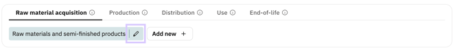
Creating individual sub-stages:
New sub-stages can be created using the ‘Add new’ button. A distinction is made between sub-stages at level 1 and sub-stages at level 2.

Sub-stages at level 1 define the main structure within a life cycle stage. Either preconfigured sub-stages can be used, which already contain predefined activities and associated emission factors. This is particularly helpful at the beginning of data collection. Alternatively, individual sub-stages can be used, which can be freely named and map company-specific process steps.


Clicking on ‘Add’ creates the new sub-stage both in the report configuration in the base data and in the Data tab.
Sub-stages at level 2 provide an additional level of detail within a sub-stage. They can only be created within individual sub-stage (level 1) and enable more precise structuring of complex processes or data entries. When creating sub-stages at level 2, you can also choose between predefined and individual sub-stages.
Note: No further sub-stages at level 2 can be added to preconfigured sub-stages at level 1.
If you add sub-phases even though activities already exist at the phase level, these will automatically be assigned to the newly created sub-stage. This automatic assignment cannot be undone. Subsequent relocation is then only possible via CSV download and upload.
Editing or deleting sub-stages:
Both editing and deleting sub-stages is done via the pencil icon.
Individual sub-stages can be renamed or deleted at any time. Their description can also be added, modified, or removed at any time. However, it is not possible to switch to a preconfigured sub-stage.
Preconfigured sub-stages cannot be renamed, but their description can be edited at any time. A default description is already provided and can be replaced if needed. Preconfigured sub-stages can also be deleted.
Note: When you delete a sub-stage, all activities contained within it are completely deleted. If a sub-stage at level 1 is deleted, all associated sub-stages at level 2 are also deleted. This process cannot be undone. It is therefore recommended that you complete the sub-stage structure before entering the activity data.
The system will display a warning message before deletion to remind you of this.

Reset to base configuration:
The report configuration can be reset to the base configuration at any time. This action removes the currently defined structure of sub-stages (Level 1 and Level 2) and replaces it with the default base configuration.

Clicking the ‘Reset to base’ button opens a dialog. There, all custom sub-stages can be removed and the default structure can be restored in one step.

To proceed with the reset, confirmation via the checkbox in the bottom left is required.
Note:
Resetting to the base configuration will permanently delete all custom sub-stages as well as all subordinate sub-stages and activities contained within them. This action cannot be undone.
Therefore, it is recommended to perform a CSV download of all activities before resetting the configuration if the data may be needed again later.
Rules for naming and structure:
-
The name of a custom sub-stage must be unique within the life cycle stage.
-
A name cannot be used if a preconfigured sub-stage with the same name already exists.
-
Structural changes become effective immediately in the Data tab.
If these rules are violated, an error message appears and the new sub-phase cannot be saved.
